Search results
Search for "cantilever stiffness" in Full Text gives 27 result(s) in Beilstein Journal of Nanotechnology.
A cantilever-based, ultrahigh-vacuum, low-temperature scanning probe instrument for multidimensional scanning force microscopy
Beilstein J. Nanotechnol. 2022, 13, 1120–1140, doi:10.3762/bjnano.13.95

- measurement of small magnetic forces and for MFM with optimized lateral resolution. To obtain atomic resolution, cantilevers with a higher stiffness are required to meet the stability criteria: or where Fts is the tip–sample interaction force. From Equation 9, the cantilever stiffness must surpass the highest
- sensor neq, the cantilever stiffness ki, and the quality factor Qi, but not on the resonance frequency fi of the cantilever. Hence, different from the thermal and detector noise terms, having a high resonance frequency is not beneficial. However, as Kobayashi already pointed out [59], the oscillator


On the frequency dependence of viscoelastic material characterization with intermittent-contact dynamic atomic force microscopy: avoiding mischaracterization across large frequency ranges
Beilstein J. Nanotechnol. 2020, 11, 1409–1418, doi:10.3762/bjnano.11.125

- cantilevers used to properly characterize it. However, one should be surprised to see hardly any hysteresis in the force trajectory of material 2 despite its obvious viscoelastic nature depicted in Figure 2. One must therefore consider whether the cantilever stiffness used is appropriate, since the force
- the cantilever stiffness over the sample stiffness. Figure 5b compares the force trajectory during impact for both values of the force constant, and indeed, we observe significantly greater indentation and repulsive forces for the stiffer cantilever. Furthermore, the force trajectory now shows an


Extracting viscoelastic material parameters using an atomic force microscope and static force spectroscopy
Beilstein J. Nanotechnol. 2020, 11, 922–937, doi:10.3762/bjnano.11.77

- using the cantilever stiffness (kc), the minimum deflection offsets (z0, d0), the deflection (d(t)), and the following relations: where kc in Equation 14 is the AFM cantilever stiffness. This data is not used directly in the fit, but can be useful for showing the indentation and force during the


Stochastic excitation for high-resolution atomic force acoustic microscopy imaging: a system theory approach
Beilstein J. Nanotechnol. 2020, 11, 703–716, doi:10.3762/bjnano.11.58

- material is larger than the cantilever stiffness. When the tip is out of contact, the resonance modes occur at specific frequencies, which depend on the geometrical and material properties of the cantilever. And when the tip touches the sample material, the frequencies of the resonance modes increase due


Subsurface imaging of flexible circuits via contact resonance atomic force microscopy
Beilstein J. Nanotechnol. 2019, 10, 1636–1647, doi:10.3762/bjnano.10.159

- . The influence of some key imaging factors was investigated including the applied normal force, cantilever stiffness, vibration eigenmode, and the elastic properties and thickness of each layer. The experimental results were then interpreted with theoretical analysis considering the dynamic model of
- Instruments, Asylum Research, Santa Barbara, CA). Their corresponding parameters are presented in Table 1, where L, L2, h, kC, f10 and f20 are the cantilever length, the length from the tip position to the free end, the tip height, the cantilever stiffness and the free resonance frequencies of the first and
- the second eigenmodes, respectively. The cantilever stiffness and the free resonance frequency were calibrated by utilizing the thermal noise method while others were provided by the respective manufacturers. Multilayer contact model The axisymmetric indentation of a tip contacting with a multilayered


Nanoscale spatial mapping of mechanical properties through dynamic atomic force microscopy
Beilstein J. Nanotechnol. 2019, 10, 1332–1347, doi:10.3762/bjnano.10.132

- the reduced stiffness of the cantilever and contact. This conversion was accomplished by modeling the cantilever stiffness in series with the contact stiffness that represents the boundary conditions at the tip–sample contact. The conversion of the measured oscillation amplitude to an effective


Mechanical and thermodynamic properties of Aβ42, Aβ40, and α-synuclein fibrils: a coarse-grained method to complement experimental studies
Beilstein J. Nanotechnol. 2019, 10, 500–513, doi:10.3762/bjnano.10.51

- range of applications of AFM technique span from biomolecules to single cells [31][56][57]. The AFM nanoindentation force–distance curves typically depend on the correct determination of the cantilever stiffness and only measurements of biological fibrils located at the centre of the fibril are


Imaging of viscoelastic soft matter with small indentation using higher eigenmodes in single-eigenmode amplitude-modulation atomic force microscopy
Beilstein J. Nanotechnol. 2018, 9, 1116–1122, doi:10.3762/bjnano.9.103

- the first three flexural eigenmodes, using an individual equation of motion for each of them, all coupled through the tip–sample forces: Here zi, ki, Qi and refer to the i-th (with i = 1, 2, 3) eigenmode displacement, cantilever stiffness, cantilever quality factor, and resonance frequency


Scanning speed phenomenon in contact-resonance atomic force microscopy
Beilstein J. Nanotechnol. 2018, 9, 945–952, doi:10.3762/bjnano.9.87

- , in the absence of a fluid layer, is defined as α = ks/kc, where ks is the sample stiffness and kc is the static cantilever stiffness (). The characteristic equation has the form . Using the measured in-contact frequencies, we can calculate the non-dimensional wavenumbers using the relation where


Material discrimination and mixture ratio estimation in nanocomposites via harmonic atomic force microscopy
Beilstein J. Nanotechnol. 2017, 8, 2771–2780, doi:10.3762/bjnano.8.276

- cantilever deflection. Fn = knAn/Qn is the drive force. kn, An, Qn and ωn are the equivalent cantilever stiffness, amplitude, quality factor and angular resonance frequency, respectively. The interaction forces Fts, depend on the instantaneous gap, d, and they are simplified as, Here the attractive forces


Exploring wear at the nanoscale with circular mode atomic force microscopy
Beilstein J. Nanotechnol. 2017, 8, 2662–2668, doi:10.3762/bjnano.8.266

- range of cantilever stiffness. Experimental images as shown in Figure 3C and in Figure 4 also show that the material is not uniformly worn along the circular wear track. Wear is more intensive at some random locations of the material, evidencing heterogeneous wear (as in Figure 3C) or production of wear
- humidity of 30%. The AFM tips were either a unique DLC coating tip with a rectangular cantilever (from NT-MDT) or a unique silicon nitride (Si3N4) probe with a triangular cantilever. Both nominal tip radius values were 100 nm and 70 nm for the DLC and Si3N4 probes, respectively, and the cantilever
- stiffness was 12 N/m and 0.4 N/m, respectively (as determined by the thermal noise method [27][28]). For each set of wear experiments, a unique AFM tip was used. After each measurement, force curves on a silicon wafer were performed to verify the state of the tip. Every data point represented in Figure 5


Functional dependence of resonant harmonics on nanomechanical parameters in dynamic mode atomic force microscopy
Beilstein J. Nanotechnol. 2017, 8, 883–891, doi:10.3762/bjnano.8.90

- simplified expression is: where kc stands for the cantilever stiffness, z is the distance between the cantilever base and the sample surface and Tn(u) = cos(ncos−1(u)). Note that An decreases for increasing order number (n) and kc values. The tip–surface interaction Fts can be expressed as a function of
- tip radius, free oscillation amplitude, cantilever stiffness and sample Young’s modulus. Because of the low amplitudes of the involved harmonics (well below 1 nm), we concentrate on the repulsive regime of the tip–sample interaction and on those harmonics close to flexural eigenmodes of rectangular


Noise in NC-AFM measurements with significant tip–sample interaction
Beilstein J. Nanotechnol. 2016, 7, 1885–1904, doi:10.3762/bjnano.7.181
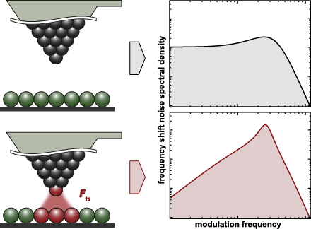
- : amplitude noise; cantilever stiffness; closed loop; detection system noise; frequency shift noise; non-contact atomic force microscopy (NC-AFM); Q-factor; spectral analysis; thermal noise; tip–sample interaction; Introduction Non-contact atomic force microscopy (NC-AFM) [1][2] is an unmatched surface


![[Graphic 32]](/bjnano/content/inline/2190-4286-7-181-i73.png?max-width=637&scale=1.18182) wit...
wit...

![[Graphic 34]](/bjnano/content/inline/2190-4286-7-181-i75.png?max-width=637&scale=1.18182) wit...
wit...


Generalized Hertz model for bimodal nanomechanical mapping
Beilstein J. Nanotechnol. 2016, 7, 970–982, doi:10.3762/bjnano.7.89

- amplitude A and interaction phase as in while the cantilever quality factor Qc, the cantilever stiffness kc, and the reference amplitude Ar are all measured in the absence of tip–sample interactions (Ar is often referred to as the “free amplitude”). Phase modulation (PM) mode Alternatively, PM mode uses an
- -PM, AM-FM configurations for the first mode (left) and second mode (right). The changes in effective cantilever stiffness for both modes (below) calculated from the observables of each mode (above) by using Equations 17–19, respectively (reference amplitude Ar1 = 60 nm). The set of approach curves in


![[Graphic 4]](/bjnano/content/inline/2190-4286-7-89-i40.png?max-width=637&scale=1.18182) approximation applied to Equation 6 i...
approximation applied to Equation 6 i...


Understanding interferometry for micro-cantilever displacement detection
Beilstein J. Nanotechnol. 2016, 7, 841–851, doi:10.3762/bjnano.7.76

- can be affected by forces originating from the radiation pressure acting on the cantilever [9]. Under conditions of Fabry–Pérot interference, this yields an optical spring effect, i.e., an effective cantilever stiffness that is increased or lowered depending on the slope of the interference fringe [10
- parameters are compiled in Table 1. The fringe-dependent effective cantilever stiffness k± is determined by a method relating the intrinsic stiffness to the optical spring constant as described in detail in [8]. In a series of measurements, we determine the noise floor by measuring the displacement noise
- determining the effective modal Q-factors and effective cantilever stiffnesses (Table 1) by procedures described in [8][14][15]. The opto-mechanical effects are observable in the cantilever stiffness exhibiting the characteristic split between the fringes due to the optical spring effect of up to 4% as


![[Graphic 27]](/bjnano/content/inline/2190-4286-7-76-i36.png?max-width=637&scale=1.18182) of the noise floor of the interferometer signal as a function of the...
of the noise floor of the interferometer signal as a function of the...
Efficiency improvement in the cantilever photothermal excitation method using a photothermal conversion layer
Beilstein J. Nanotechnol. 2016, 7, 409–417, doi:10.3762/bjnano.7.36

- 0.58 and 0.12 N/m and a visible laser beam were used. However, since the excitation efficiency decreases with increasing cantilever stiffness (or with increasing the excitation laser beam wavelength), it is important to experimentally confirm the applicability of such a coating method with a relatively


Nanoscale rippling on polymer surfaces induced by AFM manipulation
Beilstein J. Nanotechnol. 2015, 6, 2278–2289, doi:10.3762/bjnano.6.234

- with a nominal radius of 10 nm, a cantilever stiffness of 0.24 N/m, an applied load in the range between 2 and 10 nN, and scan velocity of 0.25 μm/s on 80 nm thick films. Reproduced with permission from [23]. Copyright 2007 Elsevier. The worn area is the result of scanning a given surface with a


Modeling viscoelasticity through spring–dashpot models in intermittent-contact atomic force microscopy
Beilstein J. Nanotechnol. 2014, 5, 2149–2163, doi:10.3762/bjnano.5.224

- along one fundamental oscillation. The tip was oscillated along a numerically simulated trajectory (not prescribed) for tapping mode AFM. The parameters used for (c) are: cantilever position zc = 80 nm, natural frequency (f0) = 75 kHz, free amplitude (A01) = 100 nm, cantilever stiffness (km1) = 4 N/m
- the cantilever dynamics in (a) and (b) are: cantilever position zc = 80 nm, natural frequency (f0) = 50 kHz, free amplitude (A01) = 50 nm, cantilever stiffness (km1) = 10 N/m. The model parameters for (b) and (c) associated with the DMT contribution are: elastic sample modulus (Es) of 3 GPa, elastic
- parameters for the cantilever dynamics in (a), (b) and (c) are: cantilever position zc = 80 nm, free amplitude (A01) = 100 nm, cantilever stiffness (km1) = 4 N/m. The Linear Kelvin–Voigt parameters for (a) were k = 7.5 N/m and c = 1.0 × 10⁻⁶ N·s/m. The sample parameters for (b) and (c) are the same as for


Energy dissipation in multifrequency atomic force microscopy
Beilstein J. Nanotechnol. 2014, 5, 494–500, doi:10.3762/bjnano.5.57

- cantilever, one would expect that the cantilever stiffness calculated by using the equivalent mass and the resonant frequency should incorporate the effects of the surface force gradients. In the present case, the scaling from beam theory of the elastic constant is respected with good approximation for the


Frequency, amplitude, and phase measurements in contact resonance atomic force microscopies
Beilstein J. Nanotechnol. 2014, 5, 278–288, doi:10.3762/bjnano.5.30

- cantilever stiffness. These asymptotic values of the AFAM phase however depend strongly on the actual contact damping. For the examples shown in Figure 5 and Figure 6, the AFAM phase approaches 87 degrees for a contact stiffness of p = 0.05 and 80 degrees for a contact stiffness of p = 0.25. This reiterates


Noise performance of frequency modulation Kelvin force microscopy
Beilstein J. Nanotechnol. 2014, 5, 1–18, doi:10.3762/bjnano.5.1

- snap to contact, the force gradient must be smaller than the cantilever stiffness And hence Equation 46 reduces to For comparison, a widely used merit factor for MEMS resonators is and the one of minimum force detection is This result, i.e., the maximization of f0Q/k0.69 is positioned between the usual
- largely from the FM-KFM merit factor, due to the highly non-linear probe sample interaction that motivates a wide range of cantilever stiffness and oscillation amplitudes. Absolute frequency limits irrespective of noise The example treated here seems to have rather low performance compared to, e.g., video


Dynamic nanoindentation by instrumented nanoindentation and force microscopy: a comparative review
Beilstein J. Nanotechnol. 2013, 4, 815–833, doi:10.3762/bjnano.4.93

- applied to the base of the probe or to the sample, and this motion is transduced into force by a flexing of the cantilever beam that holds the probing tip. The degree of flexure is measured, usually by optical means, and the force is obtained with knowledge of the cantilever stiffness and of the measured


Determining cantilever stiffness from thermal noise
Beilstein J. Nanotechnol. 2013, 4, 227–233, doi:10.3762/bjnano.4.23

- known temperature [10]. A practical implementation of this notion, focused on the determination of cantilever stiffness from thermal noise, demonstrated the validity of the approach by a critical comparison of the results against corresponding results from other methods [11]. While the properties fn and
- averaging. Great care has to be taken, however, in mounting the cantilever to ensure that the measured Q-factor is the intrinsic Q-factor of the cantilever rather than an effective Q-factor caused by improper mounting of the cantilever [12]. Determining the cantilever stiffness relies on an absolute
- in the calibration of the additional equipment involved. Note, however, that any noise source besides the thermal excitation yields a reduction in the measured modal stiffness and cannot explain values that are too high. The determination of the effective cantilever stiffness from frequency shift

![[Graphic 34]](/bjnano/content/inline/2190-4286-4-23-i40.png?max-width=637&scale=1.18182) measured for the fundamental mode of cantilever V 4. Measureme...
measured for the fundamental mode of cantilever V 4. Measureme...


![[Graphic 23]](/bjnano/content/inline/2190-4286-4-23-i29.png?max-width=637&scale=1.18182) measured for cantilever V 4 (A0 = 16.8 nm, demodulator band...
measured for cantilever V 4 (A0 = 16.8 nm, demodulator band...
Towards 4-dimensional atomic force spectroscopy using the spectral inversion method
Beilstein J. Nanotechnol. 2013, 4, 87–93, doi:10.3762/bjnano.4.10

- which, using the same cantilever, the user acquires multiple force curves at a single pixel by varying the amplitude setpoint. One can also conceive other types of studies in which one varies other parameters, such as the cantilever stiffness, mass, eigenfrequency ratios, etc., keeping all other


Thermal noise limit for ultra-high vacuum noncontact atomic force microscopy
Beilstein J. Nanotechnol. 2013, 4, 32–44, doi:10.3762/bjnano.4.4

- values are due to frequency-range limitations of the spectrum analyser. In the case of higher harmonics, we cannot easily calculate the modal cantilever stiffness, as it strongly depends on the tip mass, which is generally not known [13]. Therefore, determining requires the knowledge of the stiffness


![[Graphic 53]](/bjnano/content/inline/2190-4286-4-4-i64.png?max-width=637&scale=1.18182) =
= ![[Graphic 32]](/bjnano/content/inline/2190-4286-4-4-i43.png?max-width=637&scale=1.18182) f...
f...


![[Graphic 56]](/bjnano/content/inline/2190-4286-4-4-i67.png?max-width=637&scale=1.18182) using three diff...
using three diff...
